


Fred's Appliance Academy
December 30, 2019
Dryer Training
Hey, what’s going on everyone, Tim with Fred’s Appliance Academy, here with another great video for you today. In this video, we’re going to go over 240-volt Frigidaire electric dryer that has a mechanical style timer on it, and I’m going to teach you how to go over the schematic and how to read the schematic and understand the schematic, that by the time this video is over and done with when we trace out the actual circuits for the heat and the motor, you’re going to look at things and be able to kind of simplify when you’re out in the field.
And believe it or not, a lot of techs have a hard time following these schematics. It’s like a roadmap and everything leads to one area or another. You just have to look at it that way. But still, even veteran technicians as myself, as my co-instructor, some of my guys that are on the road, as well as some of the rookie techs have a very hard time reading wiring schematics which is very important in this field if you really want to try to figure out what’s going on, and you don’t want to be that type of tech where you go, “Well, it needs X, Y and Z, and ABC.”
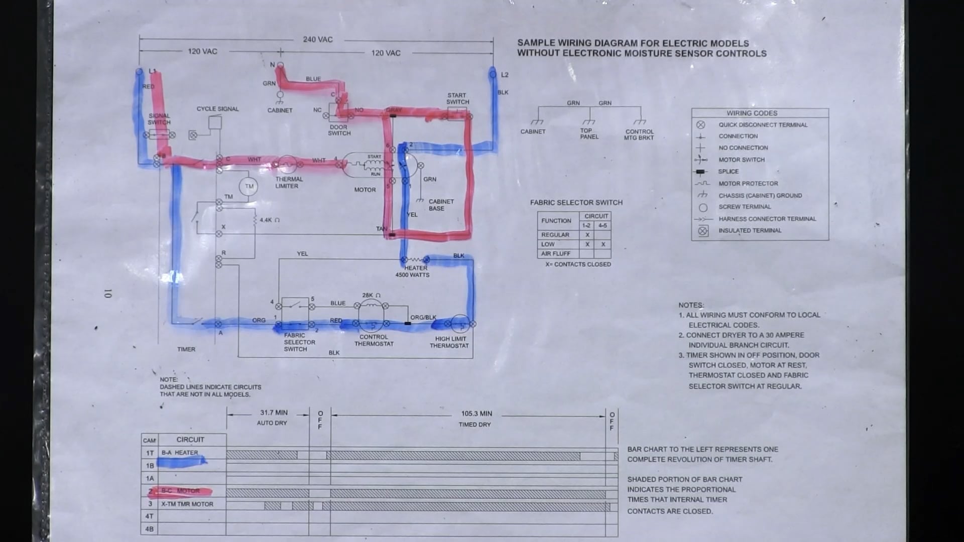
Usually, on an appliance, you’re going to find maybe one issue, and there are some times where you’ll find more than one, but most of the time it’s one issue. So we’re going to go over this and we’re going to figure out how we get power down to our heater and how we actually get power to our motor. But I want to focus on some of the different areas of the schematic here, like our fabric selector switch, some of our terms, and what the symbols mean on our schematic. But we’re going to concentrate here on our bar chart, which is also named the Esterline chart by the engineers. So we look at this and we have some shaded areas and we have different times, and it’s time dry, auto dry, and we’ve got some circuits over here. The circuits are actually for the timer. So when we look at this schematic here, this is not the timer, this is the whole unit. This is everything that’s inside the unit. And what you’re going to be looking for is the different contact letters.
So let’s take for instance our heat, which is our first one, B and A. Now if we look at B and A and if a customer says, “Hey, in my auto-dry cycle, my clothes are still coming out sopping wet. It’s not drying at all,” what I would want to do is, first of all, check power to the unit. So, you’re going to be behind there. Check your terminal block. Make sure that you got a good connections, you don’t have any discolored or melted wiring behind there. And then also, when you unplug the unit, which you’ll have to, to isolate B and A on your timer, look at the plug end. Make sure that’s not really warm. That would indicate something’s going on in the outlet.
So let’s unplug the unit. And the first thing we’ll get going to do is we’re going to locate and isolate B and A. Now, here’s a very good thing that happens nowadays, with the way technology has advanced from the time that I first started. You might be new to the game here and not really knowing how to read the schematic or where the wires actually go. Take a picture of the wiring with your smartphone, with your tablet. So that way, there, you can always remember and see where that wiring goes so you don’t mix up which wires go where.
So looking at our auto-dry cycle, these slash marks here in this 31.7 minute auto-dry cycle, this is indicating that the contacts B and A on the timer are closed at this time. Where it’s open here, these non-shaded areas where they’re just clear, that means that the contacts are open and that would be what’s called our cool-down mode. Our time dry has a same very thing. We have our slash marks throughout the entire cycle except for about the last 10 to 15 minutes of the cycle, where it’s going to go ahead, it’s going to cool down and allow cool air to go in there, so we don’t get thumping noises on our rollers, we’re not wearing out bearings or overheating the unit as it is. And it also protects the fabric as well, to your clothing.
So we would want to go ahead and attach our meter to B and A with some alligator leads, which is the easiest way to do it. So you’re not trying to hold your meter and you’re trying to turn the timer at the same time to see if B and A actually opens up during that part of the cycle. So I would attach my alligator leads to B and A and I would slowly turn that timer in a heated cycle. It cannot be an air fluff or a wrinkle or a cool down cycle. It has to be on a heated cycle. And I would turn that timer slowly, and I should have continuity, meaning less than one ohm or on my meter it would beep indicating that the contacts are closed.
So while turning that very slowly there, and if we can get all the way to the end, so about that last 10 to 15 minutes, we know that our timer’s not the issue when it comes to a no heat situation inside of a dryer. So that would actually be our heat cycle. Then that’s B and A. I’m going to show you that on timer… or on the schematic here and how we get power actually down to that heater. But I want to go ahead and move on with this Esterline chart and I want to go to B and C, which are going to be for the motor. And the heater and the motor in this video are two main focused items that we want to look at, and that we want to actually be able to trace out so you can see how power gets there using the 240 volts.
Now if you turn your dryer on to any cycle, you can see in the Esterline chart that the contacts B and C are closed through the entire cycle. It doesn’t open up until it gets to our actual off position. So you could see the slashes there. So if you suspect, if a customer says, “Hey, my dryer, I really think it’s shutting down too early, sometimes I catch it where it goes through the entire cycle. Or sometimes I just find it and it’s just turned off.” Well you’re going to unplug the unit, isolate B and C on your timer and you’re going to go ahead and see if that opens up at anytime throughout the cycle. If it should, you know your timers the issue, if it doesn’t, we’re going to have to look elsewhere. So that’s our Esterline chart.
Some of the other things that we actually have here on the schematic, which one right up here, which is a called our fabric selector switch, this is going to be the setting on your control panel for high heat, medium heat, low heat or no heat. This one, however, is labeled regular, low or air fluff. And on the back of the switch itself, so if you were to take the control panel down after you’ve unplugged the unit, you’d be able to see that there’s actual numbers on each terminal on there. So if we wanted regular heat, so that’d be our high heat and most other dryers, we would look for contact one and two and the X indicates that those contacts are closed, that we’re going to get a high heat dry at that cycle we chose.
To get the low heat, you’ll see that the contacts one and two, four and five are actually x-ed out, meaning those are closed and you’ll get low heat. So the actual cycling thermostat which is going to be in this mechanical style dryer with a timer, that’s going to cycle a little bit quicker maintaining a inner drum temperature much closer to a lower temp than we would have on our high temp high heat timed dry. So that’s our fabric selector switch.
We’re going to move you down here and show you some of these wiring codes that we have. The wiring codes, if we look at on the right hand side of our schematic, we can look at these codes here and this is what’s telling us what everything means on this timer here. So you look at quick disconnect terminals. You look at connections which is like a splicer or a T connection, no connection. That’s when if you look at a schematic, you see a wire going through a wire, those are not connected. They will either indicate that with a backward C, meaning that the wire travels all the way through. They will indicate that with a circle that’s filled in with a connection point. This one, however, does not indicate anything. It just goes straight through the line so it tells you that right here on the wiring code so you don’t get confused and think those two wires, for some reason, are connected with each other somewhere else.
We have our motor switch, which another name for the motor switch is called our centrifugal switch. We’ll look at that once we get into how we actually get the motor running. We have a splice. That’s just going to be the manufacturer splicing maybe neutrals off, or maybe your L1 or L2 off to different locations and there’ll be in a nice insulated jacket and with some heat shrink around it, but it’ll have a couple of different wires coming out of it, maybe a one or two extra wires, and those are all spliced together by the manufacturer. You have your motor protector, which is also called an overload. Most motors out there have an overload, so if the motor is working too hard or if for some reason something might be stuck in what’s called the blower wheel, this motor would just buzz and the customer will hold down that start switch. They’d start smelling an electrical odor and then they’ll hear a click. That’s the overload, which is resettable, actually opening up to protect the motor.
We have our chassis cabinet ground and we can see here that they’re all green. We have a cabinet ground, top panel ground, and a motor bracket ground. So that’s telling you where you’re going to find your grounds at. We have our screw terminal, so if we have a grounded wire or if we have our terminal block as well, a screw is going to go there and it’s going to connect the wire together. We have a harness connector terminal, sometimes a Molex connector is what you’re going to see there. Those are going to be just quick disconnects that you’re going to have. Makes things a lot easier when you’re replacing parts. And then you have an insulated terminal, which means that the terminal itself that the wires connected to is insulated. It’s got an insulator all the way around the metal so nothing comes in contact with it to possibly short it. So that’s our wiring codes.
Now there’s a lot of notes on here. It tells you that, hey, the doors open or the doors closed. It also tells you too that the wiring must conform to local electrical codes. So if you have a customer that has really old electricity, they’re still using copper water lines for grounding in homes, which I know in our area here you can’t do that, it is against the electrical code. Everything’s got to be to what your state, county, local codes are. Tells you that what type of breaker you need to hook up to, and this is a 30 amp breaker needs to be hooked up to. And then here it is, timer in the off position door switch closed. The motor is at rest, the thermostat is closed and the fabric selector switch is on regular. So we would be on a regular heat. So if we close… if we press a start switch, this unit would actually start up with a regular heat.
So what I want to do here is we’re going to go ahead and I’m going to go over the different things in the schematic and we’re going to trace out first our heat circuit. Okay. So what I’m going to do is I have this schematic in a plastic sleeve. That is probably one of the easiest things you can do when you’re trying to figure out a schematic in a customer’s home. You don’t want to necessarily go and start marking up their schematic, and another technician will go out and they won’t understand or they won’t see things or something might be scribbled out. So what I do is I used to carry a plastic sleeve with me and a couple of dry erase markers. So in one color what I’m going to do is I’m going to check the heater. So I want to see everything that is involved in our heater circuit.
So that’s going to be, we’re going to use blue for this one, B and A. So we know that in this unit, because it’s 240 volts, that the heater requires 240 volts in L1 and L2, so we’re going to start on the L1 side. And what’s going to happen is L1 comes in from the terminal block and we’re going to come to contact B on the motor, which is right there. Now once we turn that timer to a dry position, it’s going to go ahead and send power down to contact A. So B and A, there’s a switch right there that is closed, and our first stop is going to be the fabric selector switch. And again, the fabric selector switch is there to control the temperature of inside the drum. We are doing a regular heat. Remember we have contacts one and two on the fabric selector switch are closed.
Once we come out of the fabric selectors switch, we’re going to go to the control thermostat. The control thermostat is one of our first safety items inside the unit to prevent the unit from overheating, and this is what says to turn the heater on or to turn the heater off. Inside here you’ll see that there’s a switch and it’s got a sideways hat on the bottom of that switch. If you don’t know that sideways hat is indicating that switch opens on a rise of temperature and it is a resettable switch. If you were to actually find that open at room temperature, you need to replace it. They don’t lose calibration and they just outright fail, and a lot of these parts that we’re going to talk about that could fail is due to poor ventilation. So always check your customer’s vents too as well.
We’re going to come through the fabric selector switch and we’re going to go to our high limit thermostat, which is a safety device that if the control thermostat does not open up, our high limit thermostat opens on a rise of temperature which is also a reset double switch in some. Some of the high limits, and it’s depending on the manufacturer itself, they may call it a different item and it may not be resettable. It’s a one and done is what they call. It’s like a thermal fuse.
So as long as everything’s still good, we’re going to go through the high limit thermostat and we’re going to come up to one side of the heater. Now that’s getting our L1 to our heater. We need to now bring in L2 because we need 240 volts. This is a 4,500 watt heater, so it will require 240 volts. So the first thing I’m going to do is locate L2 and I’m going to use the same color here. So L2 here is coming from the terminal block. We’re going to come in and where it’s going to go through first is contact two on the motor. This units going to use a split phase motor, and most dryers do. It requires 120 volts to run, and on that motor switch or centrifugal switch what has to happen is once that motor starts up, that centrifugal switch is going to disengage our start winding and engaging our run and our heat circuit because we’re going to actually bring 120 volts through the motor on contact one and two to our heat.
And that’s how we get power to our heater there. So we’re coming from L1 through B and A on the timer through the fabric selector switch, the control thermostat, the high limit thermostat, and then that goes to one side of the heater. So anytime that you turn that unit on and for instance, if a customer says, “Hey, I just turned my unit on and it’s getting really hot, it’s not running. It’s just I turn it to a heat cycle or just on any cycle it gets hot.” You’re going to want to check to make sure that the heater has not grounded itself to the case, or that there may not be an underwire to a bra that’s stuck inside between the heater and the drum which is grounding that element out providing that other side of that 240 volts to power that heater up.
The L2 side comes right in through L2 and then when we come through one and two on the motor, that’s for the most part a pretty uniform across each manufacturer out there. That one and two for the motor would be for your heat, and a lot of the motors those are your two outer terminals on the terminal block of the motor itself. So we have our heat there. Now in order to get that heater running and to get that motor one and two to close, we have to actually come in and we have to start our motor. And to do so we’re going to start with L1. And again, L1 we’re going to come through B and C right here are for our motor. We’re going to come through B, go through C and now we have what’s called a thermal limiter or a thermal fuse.
If that fuse is open, check your venting. Check to make sure that the elements not grounded. More than likely you have a ventilation issue. We’re going to come to the thermal limiter and we’re going to come to contact four on the motor. Right now the start and run windings are in parallel with each other, and we’re going to use contacts four and five to actually start the motor. So when the motor actually does start, and in order to do so we have to use neutral because the motor is 120 volts. Neutral is going to come in through our door switch and our door switch is going to be either a single pole single throw switch or a single pole double throw switch, meaning that the single pull double throw switch has two functions. So when you were to do close the door, the light would turn off and now we would be able to engage neutral to be sent through the motor once we pushed the start switch, and then when we opened up the door, the light would turn on. So that’s your single pole double throw switch.
We’re going to come in through the door switch and this gray wire, there’s a splice, but we’ve got to come through and as soon as you press that start switch, which is just a momentary switch and you can’t just press it real quickly, you actually have to make a few second contact with it until that motor starts up, and you’ll hear that click from that centrifugal switch. So once we press start, that neutral is going to travel around and it’s going to come through back up through five and six on our motor. And now our units running. Now the unit is heating. As long as everything is done correctly, this is what you should have here. It’s very easy and again, if you made a mistake, you have dry erase marker. Use a dry eraser or use a rag, something like that, to go ahead and figure things out.
One thing I do want to point out though is if we were on a low heat cycle and not many technicians do know, but on some of these cycling thermostats you’re going to have a little resister inside here, and Frigidaire uses a 28,000-ohm resistor. Thing is I asked all my classes, “Would this customer ever know if the resistor inside there was not working?” Usually, I get, “Yeah, sure they would. They’re going to say that the clothes are getting dried too quickly.” I don’t think you’re ever going to find a customer out there that says their dryer is drying too quickly. They can’t keep up with it. You probably won’t ever really find that out there, but it is something interesting to look at and that’s actually going to be through contacts four and five on that fabric selector switch. And it’s just what that does is that tiny little resistor receives voltage, it warms up and it fakes that control thermostat out thinking that it’s warmer in there than what it really is to allow it to open up quicker to maintain a lower temp inside the drum.
So with the schematic and the clear sheets, you’ll be able to get a good sense of where things are at, what controls what and how we get power to what. This is, again, one of the hardest areas to really learn and it’s like reading a roadmap, really paying attention to cross streets and paying attention to main streets that you have or where your road might be. Is there an alternative route or they could take? Make sure that you’re asking the customer and you’re really verifying the complainant. What’s going on? “Hey, it’s just taking too long for my dryer to heat.” First thing I’m checking is the venting. I’m going to check to make sure that the venting material is a good material and I’m going to check the outside vent to make sure that I have good airflow coming outside.
If I don’t, I know that’s probably going to be the issue there, but then if I do find everything’s working well, I’m going to look for something inside this unit to not want to work properly. So I really hope that this helps. I’ve had a couple of requests for wiring schematics and a video on wiring schematics to learn how to read them and go through them. I don’t want this to be the only one that I do show you. I like to get a couple of different brands out there and show you just how we can go from a very easy Frigidaire schematic to a more difficult Samsung or LG, Whirlpool or GE sometimes and with all the different names they have for some of these components that are inside there. So right now what you guys should be able to do is just review this and you should be able to go to any Frigidaire dryer, watch this video and you’ll be able to trace out that motor circuit, trace out that heat circuit and figure out where your problem lies.
Again, don’t forget the venting. Make sure it’s a good semi-rigid metal vent behind it, can’t be that slinky tinfoil stuff, and always check the outside. Check it in the spring, check it right before the snowfalls. Animals like to get in those areas to keep warm for the winter and then they just leave their homes when it becomes summer outside, and that’s what’s going to plug up your venting. If you guys really enjoyed this video, please like and subscribe to the page here. We do this for you guys to really understand and simplify things for you and give you a little bit of an education even if it is just your average do it yourselfer, now you also have the ability to read a simple wiring schematic and knowing what some of the things mean.
Just remember, not all wiring schematics are the same. Not all timers are the same. So you may come across a timer again where it’s just labeled with wire colors on them. You have to be able to read this Esterline chart at the bottom of the schematic to find out what switches are opened and closed at what times, and what should be opened and closed during the other times. So again, from Fred’s Appliance Academy, I’m Tim, and we are here training tomorrow’s technicians and we really appreciate the support that you’ve all given us, and I really hope that you like this video. Until our next one, take care! And thanks!
Join the industry's best trainers.

(800) 781-1814Text or ring! ring!
Live ChatClick to say hi
Apr. 05, 2024
How to test a gas range ignitor

Mar. 29, 2024
Congrats to our graduating March 2024 class
Mar. 22, 2024
How to test a 120 volt receptacle

Mar. 01, 2024
Congrats to our graduating February 2024 class
Feb. 05, 2024
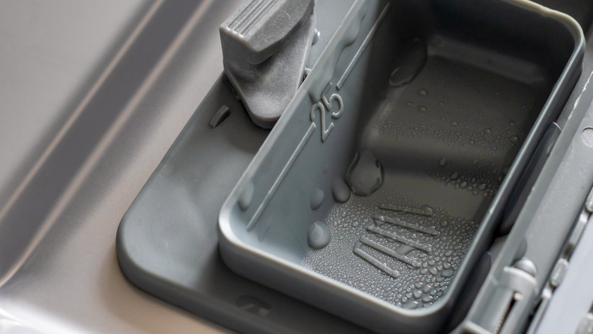
Why Is Your Dishwasher Soap Not Dissolving? (5 Easy Fixes)
Feb. 05, 2024
Refrigerator Dripping Water Inside? 5 Quick Fixes

Feb. 02, 2024
Appliance Industry 2023 Q4 Results

Feb. 02, 2024
Congrats to our graduating January 2024 class
Jan. 26, 2024
Clever ways to use airbags to level your appliances
Jan. 12, 2024