


Fred's Appliance Academy
August 14, 2020
Dryer Training
Installing four wire and three wire cords for electric dryers.
It is important that all electrical is disconnected before the installation of the cord. Contact with 240 volts can result in serious injury or death. The first portion of this video will cover the four-wire cord installation and the second part of the video will cover the three-wire cord installation.
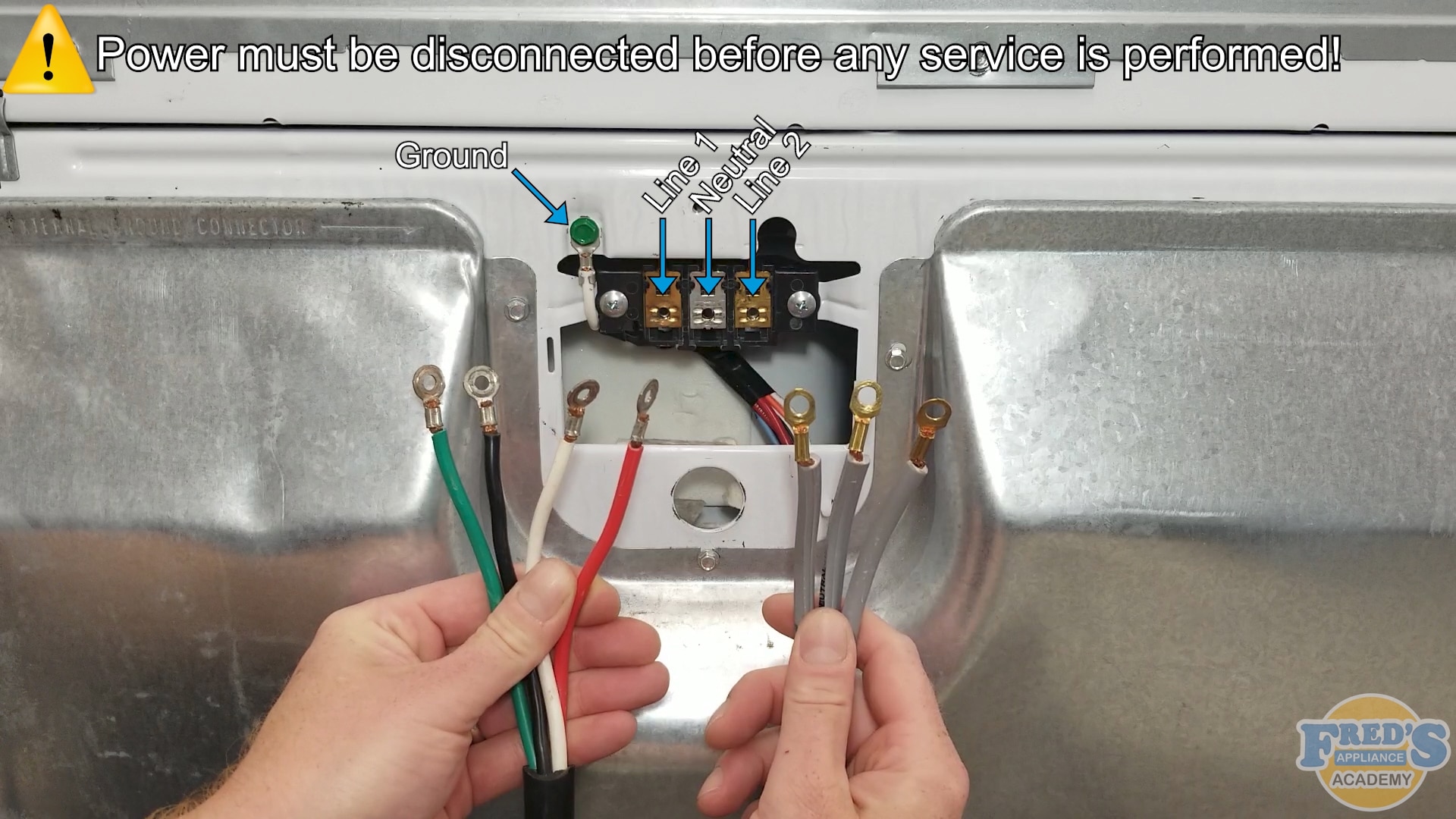
As we can see, the four-wire cord is color-coded and the three-wire cord is not. The green wire on the four-wire cord is ground. Black is L1 or line one. White is neutral. And red is L2 or line two. The center wire on the three-wire cord is neutral and will always be installed in the center of the terminal block. The outer wire on the left-hand side is line one and the outer wire on the right-hand side is line two.
Using a quarter-inch nut driver, remove the one-quarter inch screw securing the terminal block cover in place. Next, remove the three-quarter inch screws that are securing the wire terminals to the terminal block. Next using a five-sixteenths inch nut driver, remove the five-sixteenths inch screw securing the neutral wire to the cabinet. Move the neutral wire over so it comes up and underneath of the terminal block. Here we have the four-wire cord. Our black wire will represent L1 or line one. White is neutral and red is L2 or line two and green wire goes to the ground. Insert the cord through the hole in the cabinet and align the ends of the wires with the terminal block. Next, bring the two neutral wires together and secure them to the terminal block. It is important to understand that the screws that come with the terminal block are specifically threaded for the terminal block and only these screws can be used. Next, attach the line one and line two to the terminal block. Again, the black wire represents line one and the red wire represents line two.
Throughout this process you may notice that at times I turn the nut driver counter clockwise before turning it clockwise. This is to align the threads on the screws correctly with the nuts that they secure to in the terminal block. If any cross threading happens during this process, the screw and the nut it secures to will both need to be replaced.
Next using the five-sixteenths inch screw that once held the white neutral wire to the cabinet, install the green ground wire to the cabinet. Next push the cord slightly into the cabinet and install the strain relief. In many states, it is the law that the strain relief is installed. Its purpose is to prevent loose connections and avoid outcomes such as dryer fires. Once the strain relief is in position, secure it with the two Phillips head screws it came with. Be sure that the strain relief clamps tightly to the cord’s black outer insulation. Once completed, be sure to replace the terminal block’s cover.
Using a quarter-inch nut driver, remove the one-quarter inch screw securing the terminal block cover in place. Next, remove the three-quarter inch screws that are securing the wire terminals to the terminal block. Here we can clearly see that the center wire is labeled neutral. Insert the cord into the cabinet and align it with the terminal block. Neutral will always go to the center of the terminal block. Secure the neutral wire to the terminal block. Again, it is important to understand that the screws are specifically threaded for the terminal block. Turning the screws counter-clockwise before turning them clockwise aligns the threads, preventing any cross-threading from happening. If any cross-threading does occur, the screw and the nut it secures to inside the terminal block will both have to be replaced.
The outer two wire represent line one and line two. They will always be attached to the black and red wire on the terminal block. Once the cord is installed, attach the strain relief as stated in the four wire section. In many states, it is required by law that this is installed. Its purpose is to prevent loose connections and outcomes such as dryer fires. Secure the strain relief with the two Phillips head screws it came with.
Once completed, replace the terminal block’s cover.
Join the industry's best trainers.

(800) 781-1814Text or ring! ring!
Live ChatClick to say hi
Apr. 05, 2024
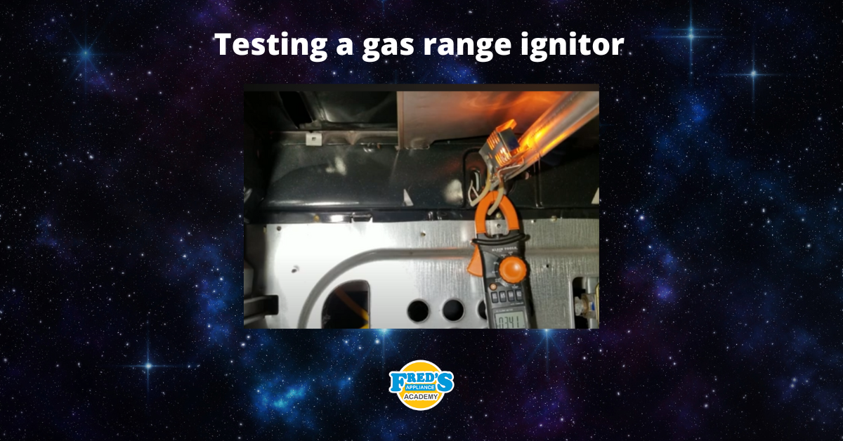
How to test a gas range ignitor

Mar. 29, 2024
Congrats to our graduating March 2024 class
Mar. 22, 2024
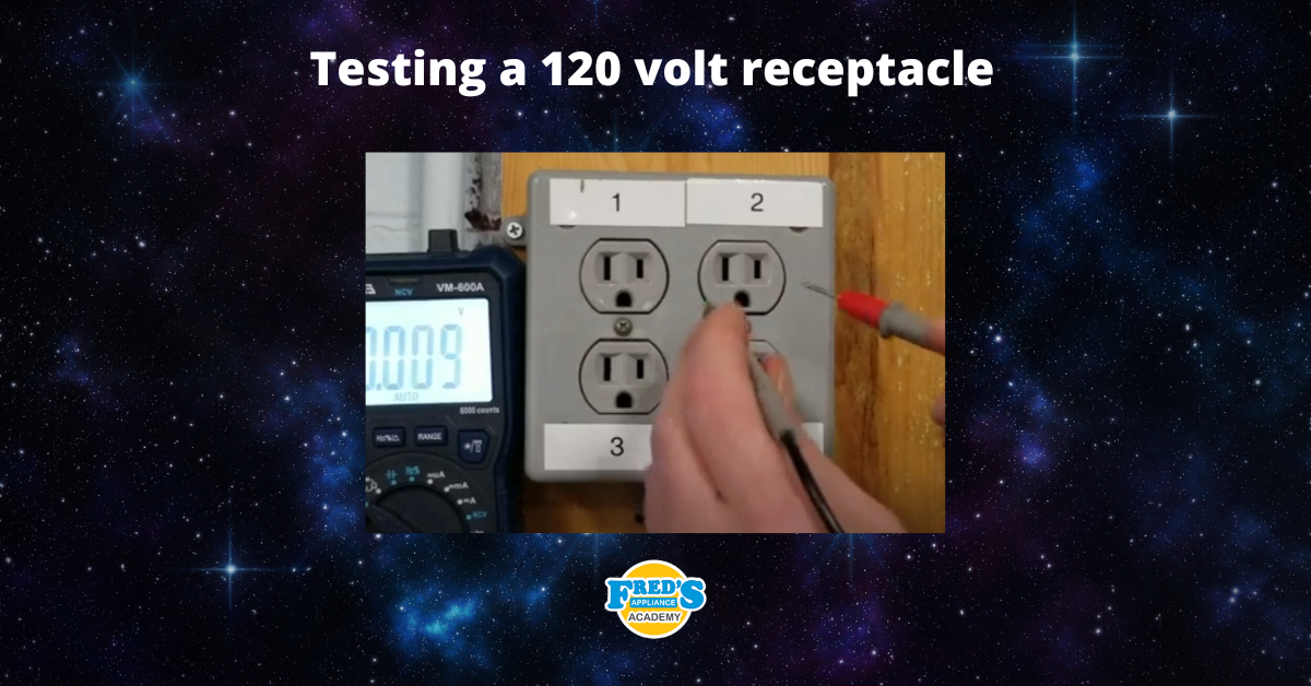
How to test a 120 volt receptacle

Mar. 01, 2024
Congrats to our graduating February 2024 class
Feb. 05, 2024
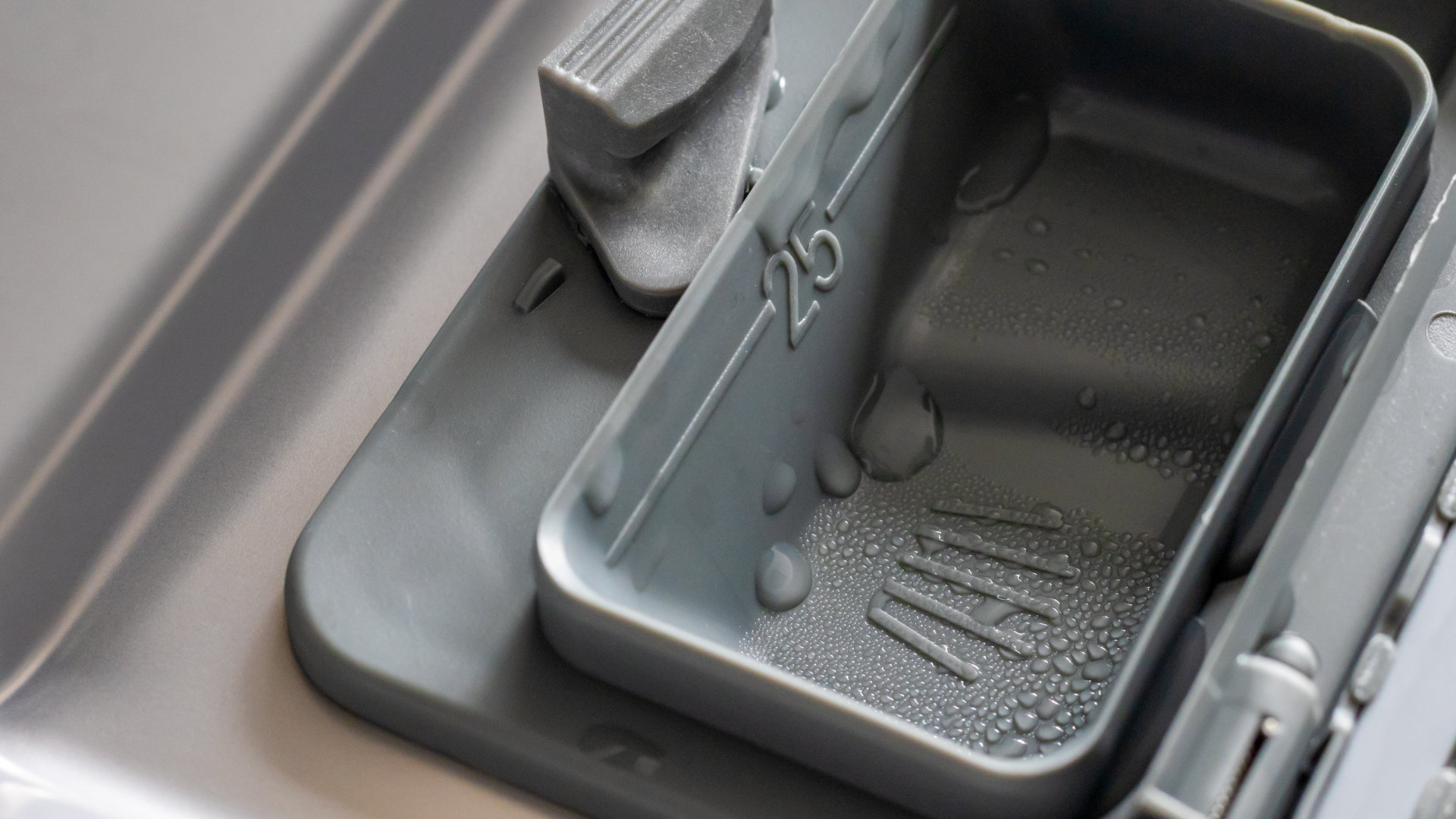
Why Is Your Dishwasher Soap Not Dissolving? (5 Easy Fixes)
Feb. 05, 2024
Refrigerator Dripping Water Inside? 5 Quick Fixes

Feb. 02, 2024
Appliance Industry 2023 Q4 Results

Feb. 02, 2024
Congrats to our graduating January 2024 class
Jan. 26, 2024
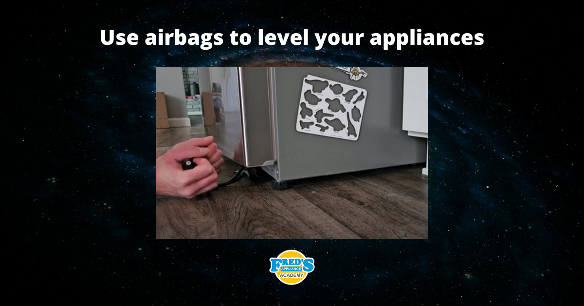
Clever ways to use airbags to level your appliances
Jan. 12, 2024